Somerset And Dorset Joint Railway
There have been one or two attempts to build the S&D before, as far as I know none got very near completion. Hopefully will get further this time.
Digitiser, Terrain, Main line
I've set up a digitiser session to cover from Bristol in the North-West to Bournemouth in the South-East (see Preparing Maps although I used better quality maps than the ones shown in the turtorial).
I started at Bath.
- Imported DEM terrain as far south as about Chilcompton.
- Digitised the main route Bath > Chilcompton and Bath > Mangotsfield
- Graded the main route from Bath to Radstock (see Digitising The Route).
- Added signals (block posts) at Midford, Wellow, Radstock etc
- Bath - Mangotsfield - only roughly laid out as I'm not particularly interested in this route - I just want somewhere for the trains to go and come back from. I've added signals at the stations along this line to allow the trains to run.
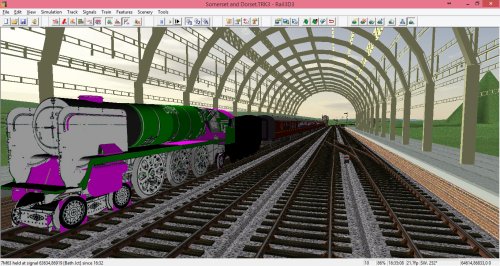
- Bath: I have laid out Bath Jct, the engine sheds and Bath Green Park station and signalled it from available signal diagrams. Operation is interesting - see below. At one stage I had the signal box linked up as a lever frame and operatable, but have now changed some of the pointwork so this isn't working. Not sure how to shunt the goods trains at the moment. Was in Bath over the new year and able to visit Bath Green Park (now a supermarket car park) and take pictures of the train shed - have started making a model of the station building.
Rolling Stock
We have some models required.
- LMS Black 5. We have a resonable model (although needs some work on the valve gear)
- SR West Country. Another of my partially completed models, I have a rebuilt West-Country in progress. When (If) I finish that I ought to do the un-rebuilt version.
- Standard types
- Ideally would need 9F, 4MT, 5MT etc. There are some old models of these, but not nearly good enough, so will do as "placeholders" for the moment, but need a lot of attention.
- Midland 4F. In progress. See Steam Engine With Sketchup
- Midland Jinty. Yes, there is a suitable model.
Bath Green Park
I now live not that far from Bath and was able to visit Green Park station over the new year break and take some photo's. I've started building a model in Sketchup:
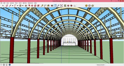
That's also the current state of the West Country
Operation of Bath Green Park is interesting as well. What we want is:
- Incoming train arrives in station, loco uncouples and pulls forward (as above).
- Another loco comes from the shed and couples to the stock, leaves with train.
- Released loco goes to to turntable and turns, then goes to the shed and waits until next required
This is complicated by the layout:
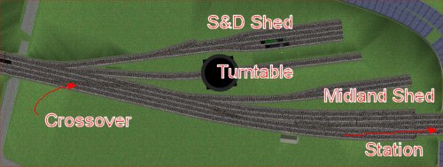
- Loco's from the shed need to use the crossover to get out of the shed, and reverse on the bridge over the road on the left of the diagram before running into the station
- Loco's coming out of the station, reverse on the bridge and then crossover to the shed, go to the turntable to turn, then stable on the Midland shed or the S&D shed as appropriate.
The way this is achieved is as follows:
- The trains have routes 1Sxx or 1Mxx. The 1S trains are routed over the S&D. The 1M trains go over the Midland to Bristol.
- The corresponding light engines have route codes 0Sxx or 0Mxx. These routes have a timetable point of :
Bath Shed 99:99
This means when the loco arrives on shed, it will stay there indefinitly (since a time of 99:99 never occurs)
- The incoming train (1M or 1S) arrives in the station and uncouples, pulls forward and reverses.
- The loco (actually the tender) has a script with an OnStuck() function. Once the loco has reversed and has waited a minute or so, the script fires the OnStuck event.
- In the OnStuck event the script looks for any locos available on the shed. (ie any train with route 0xxx, location="Bath Shed" and start time of 99:99). When it finds a train that meets these conditions, it calls that loco to come and take over the train by setting its start time to the present time. There is also some extra code in the script to prevent two loco's being called etc.
- The selected loco leaves the shed, crosses over to the up line and reverses onto the stock. On the way the route is changed to "1Mxx" or "1Sxx". The train departs.
- The now released loco can now shunt out of the station and go to the turntable to turn, and then to the shed (S&D shed for "0Sxx" locos and the Midland shed for "1Mxx" locos). Routing is controlled using {loco} and {tender} terms to route the loco to the turntable for turning and to the shed once turned. When it arrives on shed, the timetable sets the start time to 99:99 so the loco waits until called for further duies.
Tweaking the Landscape
Importing DEM data saves a lot of work, but isn't accurate enough for the detail.
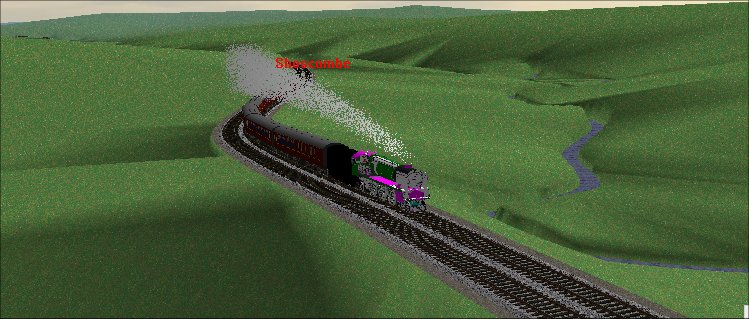
I'm now working along the line tweaking the embankments and cuttings. I tend to to do this by "riding a train" - so I select a train about to leave Bath heading south, and follow it along the line, checking the maps as I go. Where I find a cutting or an embankment I'm not happy with, I adjust the terrain - as below - and carry on. When I've completed the run over the length of the line - at the moment, I'm working on Bath to Radstock - I run triangulation (which takes quite a long time) and then pick the next train going the other way.
Here's an example where the terrain needs a tweak near Wellow:
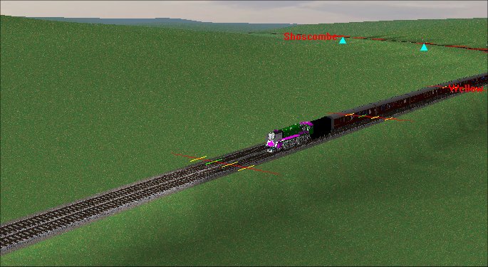 (Northbound train)
Compare this with the map at http://maps.nls.uk/geo/explore/#zoom=15&lat=51.32438&lon=-2.36672&layers=11
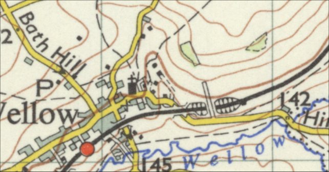
The loco is about at the position of the bridge over the road to the east of the village. So at the moment the line is above the terrain surface - that's fine for the overbridge, but immediatly ahead of the loco should be a cutting and an overbridge.
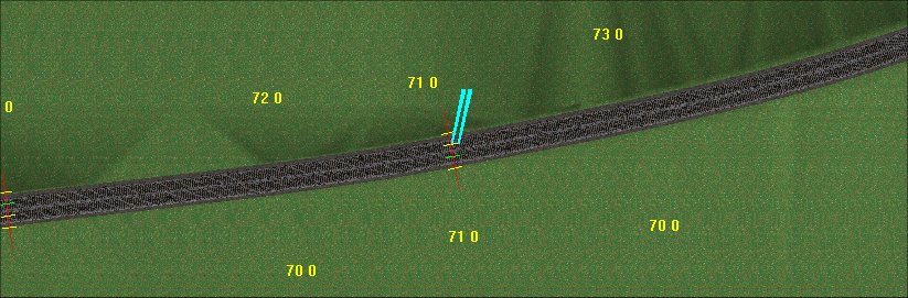
Compare with the terrain poins I have got:
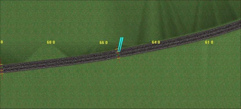
The marker is on a node about where the overbridge is, and this node is at 65.92 meters. The terrain point next to it at 66 metres clearly isn't gong to create a cutting, it needs to be at least 70 metres. So I'm going to erase the 66, 64 and 61 terrain points and add some new, higher, terrain points so that a cutting is formed.
I won't know what this looks like until after I've next triangulated and come back along the line.
Rivers are useful aids to tweaking the landscape.
- Rivers are always at the bottom of valleys
- The DEM import - which samples at 90m intervals - doesn't necessarily always hit the valley bottoms.
So I trace rivers from the map, mark elevations at keypoints (Eg where the river crosses a contour line, or passes under a railway or road) and grade from end to end with the "Grade between markers" tool. Noting, of course, that the river will always be uphill in one direction and downhill in the over.
Having graded the river, I run something along the river (usually a BMW or landrover!) and use the terrain setting tool in river mode to stitch the terrain to the river.
This usually does a lot to improve the quality of the terrain.
Another example is Lyncombe Vale - see Digitising The Route
Gradients and Elevations
I've now laid the mainline from Bath as far as Evercreech Jct using the digitiser and now travelled the length of that line adjusting curves and straightening where it should be straight. The next job is going to be elevation.
I have a gradient profile (scanned from a book) and have measured off the positions of the gradient changes (in miles) and the gradients from the scan as described in Digitising The Route. As usual this doesn't quite work :-(. In the spreadsheet, Masbury summit comes out at 255 metres, where Masbury is one of the few points where I know the actual elevation (811ft or 247 metres). So the calculation has an error of about 8 metres at this point. And there are similar issues at other points, eg Evercreech Jct the calculated elevation is about 10 metres above where it ought to be compared to the terrain surface.
The first thing to do is check and double-check the spreadsheet to make sure I have measured the distances properly and entered the correct gradients. So I've done this and can't find an error in the calculation. So I'm going to have to adjust the elevations to get the desired result.
I'm going to do this by adjusting the slope and length of the gradients in my spreadsheet until I get the desired elevation of 247 metres at Masbury summit. My "rules" for adjusting the graidents include:
- Changing the length of the gradients will be less noticable than changing the slope.
- The major climbs (eg 217½ miles at 1 in 50 between Shepton Mallet and Evercreech) should be left unchanged as far as possible.
- Track elevation should be compared with the DEM terrain and the maps to see where cuttings/embankments are desirable.
Evercreech Junction
Now that I'm happy with the general shape of the straights and curves, and the gradients and elevations, I can move onto the interesting stuff - adding station detail and sidings. The next station I want to do is Evercreech Junction.
For this, I'm going to use an "OverLay Plan" - I've scanned a scale plan of the station and junction from a book:
 (the full size image I'm using is more than 7000 pixels wide)
To use this as an overlay plan, it needs to be rotated so that it is north up:
and I need to calcualte the scale of the bitmap in metres.
Once I have this I can use Rail3D's "OverLay Plan" feature (Tools menu) to put the plan in the model:
Usually needs a bit of trial and error tweaking the x and y values to get the plan in just the right place, and I've set the elevation at just below the track.
Rail3D now shows the plan superimposed on the layout:
I can now use the plan as a guide to the positions of the switches and sidings and lay out the station and junction.
loneaussie 16/02/2015 01:02:03