Building A Model With Strips And Skins Part1
This tutorial will take you step-by-step through the construction of a complete model using the new “Strips and skins” techniques. It’s not the only way, or perhaps even the best way, of building such a model, but it should give you a clear idea how to put all the new methods together in practice.
You will get most out of this if you are already familiar with the basics of modelling in Rail3D, and have had at least a quick look at Getting Started With Strips and More About Normals. However, I think it should be accessible to beginners as well. Please complain if something is not clear!
For the moment, this tutorial ends rather abruptly in the middle of part 4. The rest will get done one day, I hope… Mark Hodson
1 The Prototype
I’ve chosen to use a MunichU- Bahn car of Type A for this tutorial. This is a reasonably straightforward modern passenger vehicle, without too many complicated bits, but it does introduce a few common problems like transparent windows, opening doors, and animated bogies.
The finished model
These units have been around since the seventies, and are still the mainstay of the U-Bahn system — if you’ve ever been to Munich then you’ve almost certainly travelled on one.
2 Planning the model
The unit consists of two permanently-coupled sections, which for our purposes can be considered as identical. So we could think of using a structure like this:
 name	Munich_UBahn_A
 Description	Original series built 1967–1983
 Unit 	!Munich_UBahn_Acar&Munich_UBahn_Acar

 [end]

 name	Munich_UBahn_Acar
 Hide
 …

 Bogie	0/330/0	<200 Munich_UBahn_A_bogie
 Bogie	0/1530/0	<200 Munich_UBahn_A_bogie

 …
 [end]

 name	Munich_UBahn_A_bogie
 Component
 …

 [end]
This would work, but would leave us with one minor problem — for reasons that no doubt make a lot of technical sense to someone in the administration, the mvg number the “North end” car sections in a different series from the “South end” sections. Since the car number of the leading car in a train shows up in the train roster, it would be nice to model this correctly, so I decided to build separate components for the two ends, both calling a single “body” component.
Another minor complication is that the bogies at the outer ends have shoebeams, those at the inner ends don’t. So I ended up with a component tree that looks more or less like this:
3 Making a skin texture
Another approach would be to define the Skin at the level of Munich_UBahn_A, but this would mean using Sub Unit syntax instead of the simpler Unit definition.
The Munich cars exist in two different livery versions. I would also like to leave open the possibility of modelling the Nürnberg dt1 cars, which are essentially the same thing in red. This means that I had to use a Skin texture. From the tree diagram above, the logical place to define the Skin is in the car sections Munich_UBahn_Aa and Munich_UBahn_Ab.
The objective when preparing a skin texture is to produce images of all the parts of the car that we are going to model, compressed into a convenient rectangle without too much wasted space. I normally start off with everything well spread out, using a drawing of the original as a template, then I copy the bits I’ve made and shuffle them around until they fit together in a neat and logical way and export them into a bitmap that I can use in Rail3D.
Fortunately, these cars are symmetrical about the length axis, without any conspicuous lettering on the sides, so we only need to make textures for one side, the inner and outer ends, the interior side, and a few details like the bogie sideframe and the seats.
3.1 Setting up
I use the package Deneba Canvas X (see Other Software for some alternatives). Most of what follows should be applicable to just about any vector drawing program, although some commands may have different names. I won’t go into the details of how to produce the different shapes you need — there are plenty of good tutorials on websites dedicated to particular graphics packeages.
The first step is to get hold of a drawing of the car you want to model. I found a nice drawing in a book 1 and scanned it into a black-and-white bitmap. When scanning drawings, it’s a good idea to use the biggest resolution your scanner supports, then only reduce the size of the image to a managable size once you’ve straightened it in a bitmap editor.
Import the scanned drawing into your drawing program to use as a template. I find it convenient to scale the drawing so that I can read off the dimensions of the original directly (if your program doesn’t support this, you can always use Richard’s Drawing Ruler program).
I add horizontal guide lines to the drawing to mark rail level on the side elevation and the centreline on the plan view, as well as a vertical guideline for each end of the car and the bogie centres.
It would be useful to have an end elevation of the car as well but, unfortunately, Pischek & Junghardt don’t include one, so I have to deduce the front-end layout from the side and plan views, with the help of photos. I added vertical guidelines to the right of the side elevation so that I could sketch in the end detail directly next to it.
3.2 Layers
It’s very important to use layers effectively when preparing artwork for textures. Separate all the elements of your drawing according to their function, so that you can work on one group of features independently of the others, and you can toggle the visibility of each group separately. I used a layer stack like this:
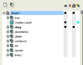
- At the bottom of the stack livery, newliv and int are for the basic colours of the exterior and interior body sides. You would only have one of these visible at once, of course.
- Windows have to be higher in the stack than the body sides, of course. I use doorblanks for the transparent regions of the door openings — you could equally put these into the windows layer.
- Details is for the various little elements to be overlaid on the outside (panel edges, door buttons, headlights, and all the rest).
- dwg contains the original line drawing I am using as a overlay. If you put this at the top of the stack and set the transparency to Multiply then the white areas of the drawing become transparent, and the drawing serves as a template for the dimensions of other parts in the artwork.
- exp is the layer I use for laying out the final texture for export to a bitmap.
3.3 The livery layers
These are very straightforward. The livery consists of stripes of blue and white (the Bavarian national colours) with the upper part of the roof grey in the old livery, white in the new one. Thus all we need are a few rectangles.
Try taking your eye-dropper to the company website — operators often use the same colours in advertising material as on their vehicles It’s important to try to get the right colours! If you don’t have any further information, then the usual technique is to find a few digital photos of the prototype and use the “eyedropper” colour sampling tool to find a region of the colour you want. Ideally, you have to look for an area that’s lit by bright, diffuse sunlight — it usually takes a bit of trial and error. If the resulting colour looks too bright or too dark, try going into hsl colour mode and adjusting the “L” (Lightness) value a bit, leaving H and S unchanged.
Put a couple of test areas of the chosen colours next to a photograph to see if it looks right
The “old” livery — notice how I’ve extended the rectangles beyond the drawing to form the front end and the roof. The white lines are guidelines which will not be visible in the final texture
To make the “new” livery, I just copied everything from the livery layer to the newliv layer, and rearranged the blue and white parts to match the new scheme. The interior layer just has a single rectangle, but filled with a nice early seventies woodgrain effect.
(Continued in Building A Model With Strips And Skins Part2)
Mark Hodson August 12, 2005, at 08:26 am
import