Run-round Loop
When a loco-hauled train arrives at a terminus, the engine has to be detached, moved to the other end of the train via a loop line, and coupled onto what is now the front end so that the train can depart back to where it came from. Even though railcars and “push-pull” sets have made it a rare sight on the main line, everyone who has ever been on a museum steam railway will be familiar with this operation of “running round”.
If you want to model a rural branch line in Rail3D, you will need to have some means of reproducing this sequence. Fortunately, it is very straightforward to set this up.
1 Basic layout
To keep things simple, we will confine ourselves to a station with only a single platform and a run-round loop. We can imagine it as the terminus of a single-track branch line.
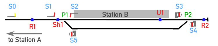
The basic elements we need for the run-round loop
This layout uses the basic elements we already know about — signals, switches and reversers — together with two new elements needed to allow shunting operations, the uncoupler and the shunt feature.
2 Setting up the track elements
2.1 Switches
There are turnouts at P1 and P2. These are very easy to set up:
- Incoming trains and light engines always take the straight route at P1, so we can leave it in its default state.
- Light engines traversing P2 in the facing direction always take the loop track, so we can simply put a * in the “other route” box to tell it to send all trains into the loop.
Settings for switch
P2The major new feature in this layout is the uncoupler, marked as U1 in the diagram above. As the name implies, this feature allows us to uncouple part of the train automatically. All that we want to happen in this case is for the locomotive to be uncoupled and continue forwards. We assume for the moment that all arriving trains have exactly one locomotive that has to be run round to the other end of the train. That means that we can simply accept the default options for the uncoupler:
Settings for uncoupler U1
Note: looking at this, you might think that we would get into trouble if we have a loco with a tender. The train would look pretty silly if we ran the loco round but left the tender where it was! Fortunately, Rail3D is clever enough to treat loco & tender as a single unit when uncoupling.
We need two reversers: R2 is at the buffer stops and simply reverses all trains, but R1 is more interesting. We need R1 to reverse light engines, but let complete trains pass through to station A.
We saw one way to do this in Basic Station Crossover — make sure that the complete train has a different route name from the light engine, and set the reverser only to reverse the “light engine” route. If we did this, we would need two Route Change features, one near S3 to change the name of the route from “Train” to “light engine”, and one near S1 to change it back again. Apart from the need to set up two extra features, this has the inconvenience that we have to be careful about the name of the “train” route — if a train arrives with an unexpected route name, the route change won’t work properly.
Much better would be to leave the route names as they are, and find some other way to detect whether we have a full train or only a loco. A neat trick is to use expressions (see Expressions and Wildcards in the User Guide). An expression is a one-line “mini-script” that can be used to define the conditions under which a track feature operates. We know that our full train is always going to be more than one vehicle long, while the engine is exactly one vehicle long (because that’s how we set the uncoupler up). So we get the reverser to measure the length of the train and only reverse it if the length is 1. We can do that by selecting Only Routes Listed and putting {len=1} (don’t forget the curly brackets!) in the route box.
Settings for reverser
R12.4 Shunt feature
This is the other essential bit that is required to perform basic shunting operations. A Shunt feature puts the train into a special mode, in which it can run into an occupied section and couple up to rolling stock standing there. The shunt feature has to be preceded by a controlled signal with the shunt option set. In our case we place the shunt feature at Sh1 and use signal S1 as the controlling signal. We want the loco to reverse direction after coupling up, so we can leave the propel option unselected, but we have to make sure that only light engines are put into shunt mode, so we can set it to apply only to {len=1}, as with R2.
Options for shunt feature
Sh1This example uses semaphore signals — the most likely system to be found on a small branch line in steam days. However, you could do it with just about any style of signals.
- First of all, we need a signal at S1 to control movements from the main line into our station. This acts as the home signal (see Basic Through Station). It also controls the shunting movement of the light engine coupling on to the coaches, so I’ve chosen a model with a subsidiary “calling-on” arm.
- The signal has to be a controlled signal.
- The Section option should be cleared, because it is a home signal. In this particular case there is no section signal in the left-to-right direction.
- Lock-through is set so that Station A cannot set a route ending at this signal (which would lead to an impasse if there is still a train in the platform).
- We also have to set the Shunt option so that the signal can set a route onto the occupied track via the shunt feature (see above).
Signal S1 settings
- Signal S2 is the starter signal, controlling movements from the station platform onto the main line. We don’t have to make any changes to the settings here, although if you’ve set the station up the same way round as me, you might want to choose a signal model that is on the right of the track. If you’ve chosen to use colour-light signals instead of semaphores, you will have to remember to make this signal controlled (the same applies to S3-S5).
- Signal S5 will be used to permit the light engine to run out on to the reversing point R1 on the main line in order to back onto the train.
- Signals S3 and S4 control movements from the platform to the loop track via the reversing point R2 at the buffer stops.
- S3 to S5 are all simple controlled signals, with no need for anything fancy. Because they only control low-speed shunting movements, it is appropriate to use ground signals for these. In real life, S3 and S4 might well be omitted and points P1 worked by hand — if you want to model this, it is advisable still to use S3 and S4, but to set the hidden option.
- Last, but not least, signal S0 is the distant signal, which should be set a few hundred metres back along the line to tell drivers to start braking for the terminus. As there is no section signal, this distant will never clear — in real life a signal with the arm fixed at caution would be used. This makes sense intuitively: trains always have to stop at a terminus, after all!
3 Trying it out
Layout set up in Rail3D
Given all this, it is very straightforward to build a station with a run-round loop. A quick test shows that everything works.
A train arrives…
The loco is uncoupled and runs forward to the buffers
The loco runs round the coaches through the loop
Once the loco has reversed again, the calling-on arm of S1 clears…
…to allow it to couple up to the train
S2 clears for the train to leave.
4 Taking it further
The set-up described above works correctly, but has a few limitations. One of the most obvious problems is that it does silly things if you send it a train that doesn’t have a loco on the front. If your branch line uses a mixture of loco-hauled trains and dmus or other fixed-formation sets, you will need to put in a reverse before U1 to catch the dmus. In this case you would probably select on route names.
When the loco runs out from S5 to reversing point R1, it has to occupy part of the “main line”. In our simple case, this isn’t a problem, since the section from A to B can only be occupied by one train at once, thus the driver of our engine will retain the single line staff until the train is back at station A. In this case there would be a “limit of shunt” board at R1, and the signalman at B would be allowed to carry out shunting operations on the main line up to this point without the need to get permission from A to occupy the section.
In a more complicated case, e.g. if station B had aditional tracks that could allow a train to be taken off the main line so that a second train could follow from A, it would be convenient to add an additional Outer Home signal for incoming trains and an Advanced Starter for outgoing trains, both somewhere between S0 and R1. These signals, if used, should be set up with the lock-through option switched on to prevent an impasse.
At the other extreme, a light railway might dispense with signals at a location like this altogether. The points would be operated by the train crew, and the train would depart towards station A after getting permission from the line controller by radio or telephone. In Rail3D, you could simulate this by making all the signals hidden.
Have a look at the Holmfirth and Charnton RoadCharnton Road demo layouts using Lever Frames to see some other ways to set up the signalling of a small terminus more realistically.
import